CASE STUDY 1 - ADDING FLUSH SOCKETS ON A TILED PLASTERBOARD WALL
Location:
Winchester.
Job Description:
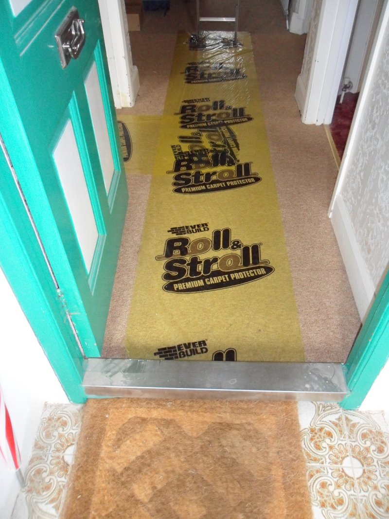
This is a typical example of adding sockets on a tiled plasterboard wall without insulation.
This is not a job for the unskilled, amateur or DIYer.
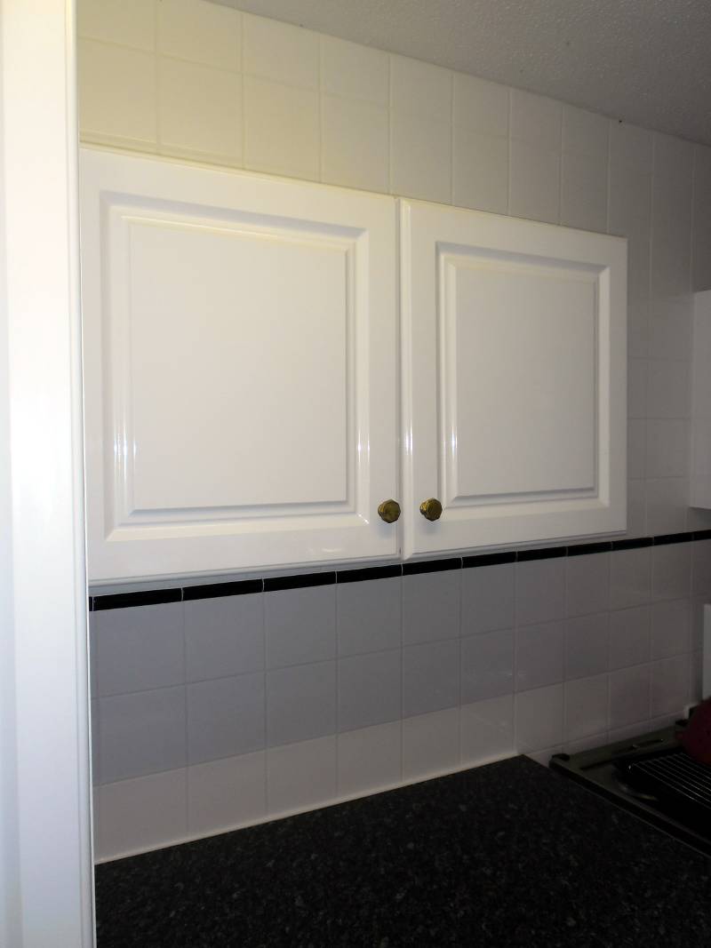
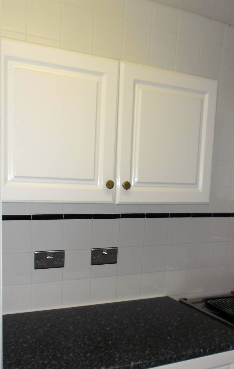
This kitchen was completely re-tiled above and below the kitchen units a few years ago
and the owner needed extra sockets above the worktop.
The extra sockets had to be fitted without damaging the existing tiling, wall or kitchen units.
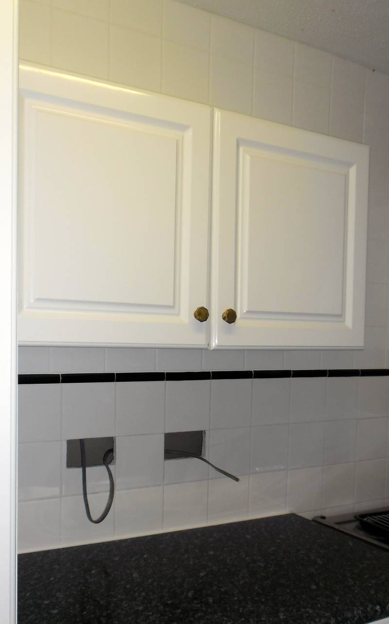
First - the cabling needs to be routed to the new socket positions.
If there's no cable to power to the sockets they are not much use.
As it was a stud wall, the cabling could be routed in the void,
but special diamond cutting tools are required to cut tiles.
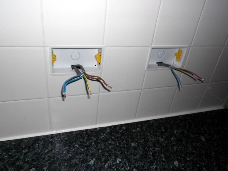
Now it's a matter of fitting the drylining boxes and preparing the cable for second fix.
Extra sockets above the worktop done as requested without damage to the wall, cupboards or tiles.
CASE STUDY 2 - REWORK A SINGLE 13A SOCKET ON THE SKIRTING BOARD
Location:
Chandlers Ford, Southampton.
Job Description:
This 1930's property was rewired in the 1970's and the original 15A round pin sockets
replaced with modern 13A square pin sockets, but in the original 1930's positions
(surface mounted on the skirting board).
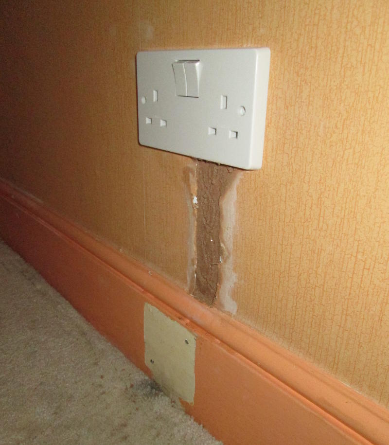
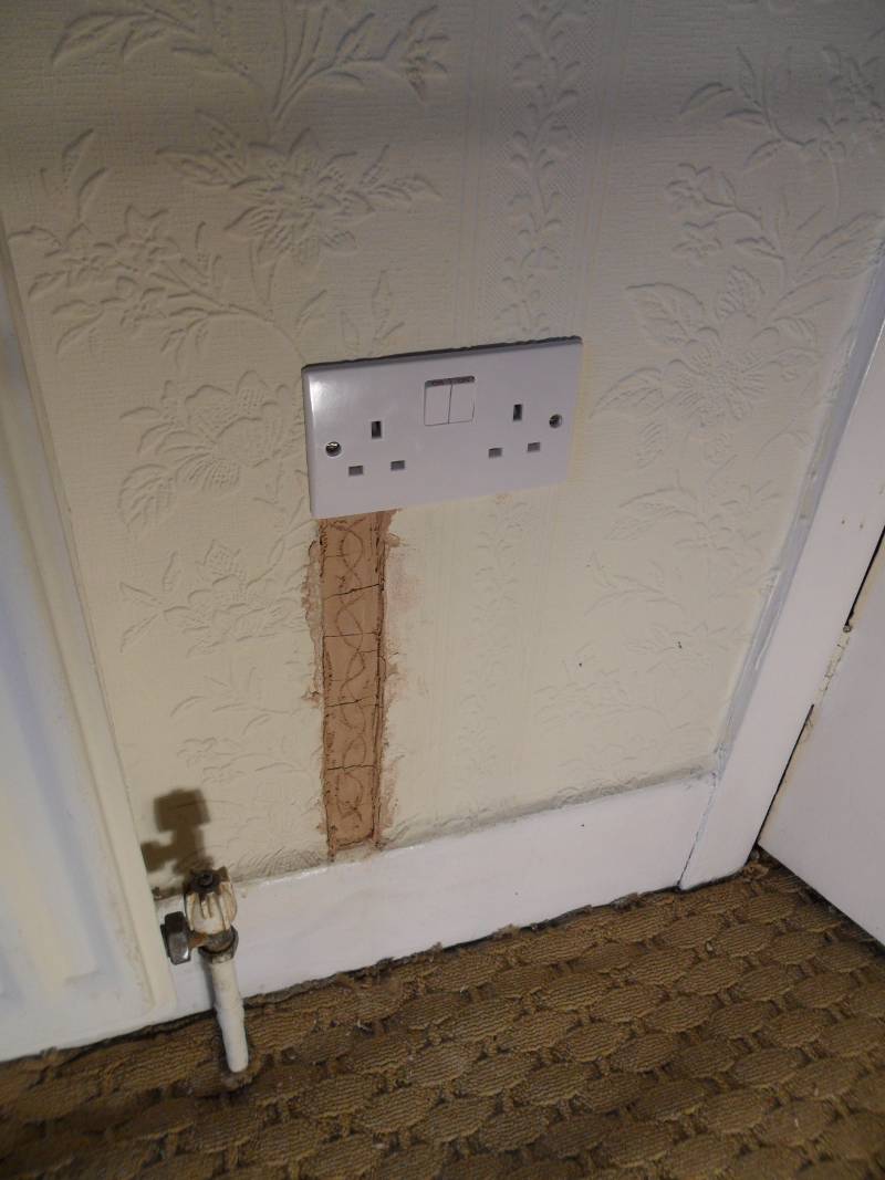
The job was to remove this single surface socket and replace it with a double 13A socket,
flush mounted at a customer defined height above the floor with minimal damage
to the existing decoration.
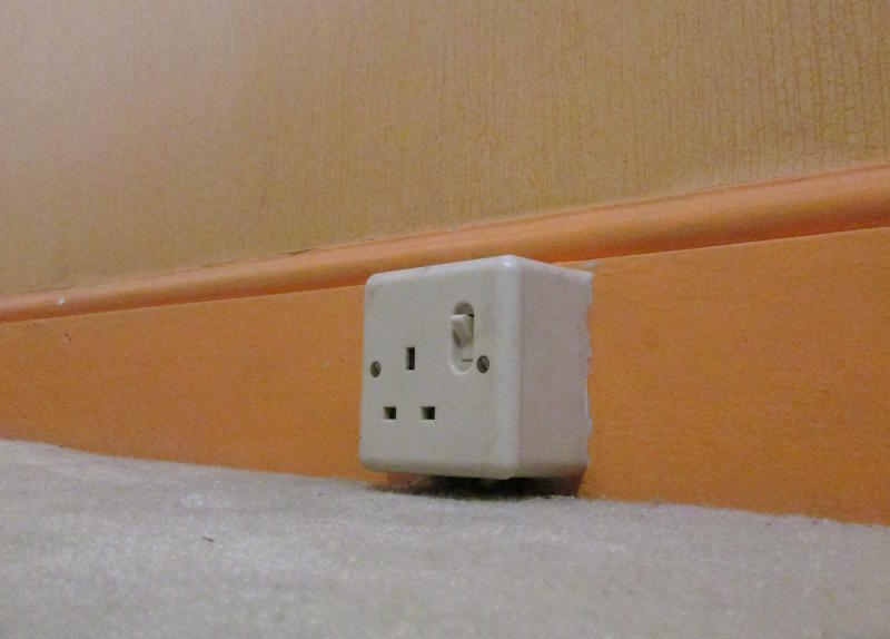
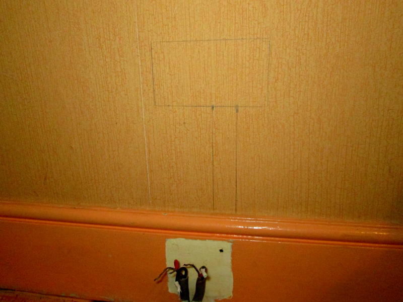
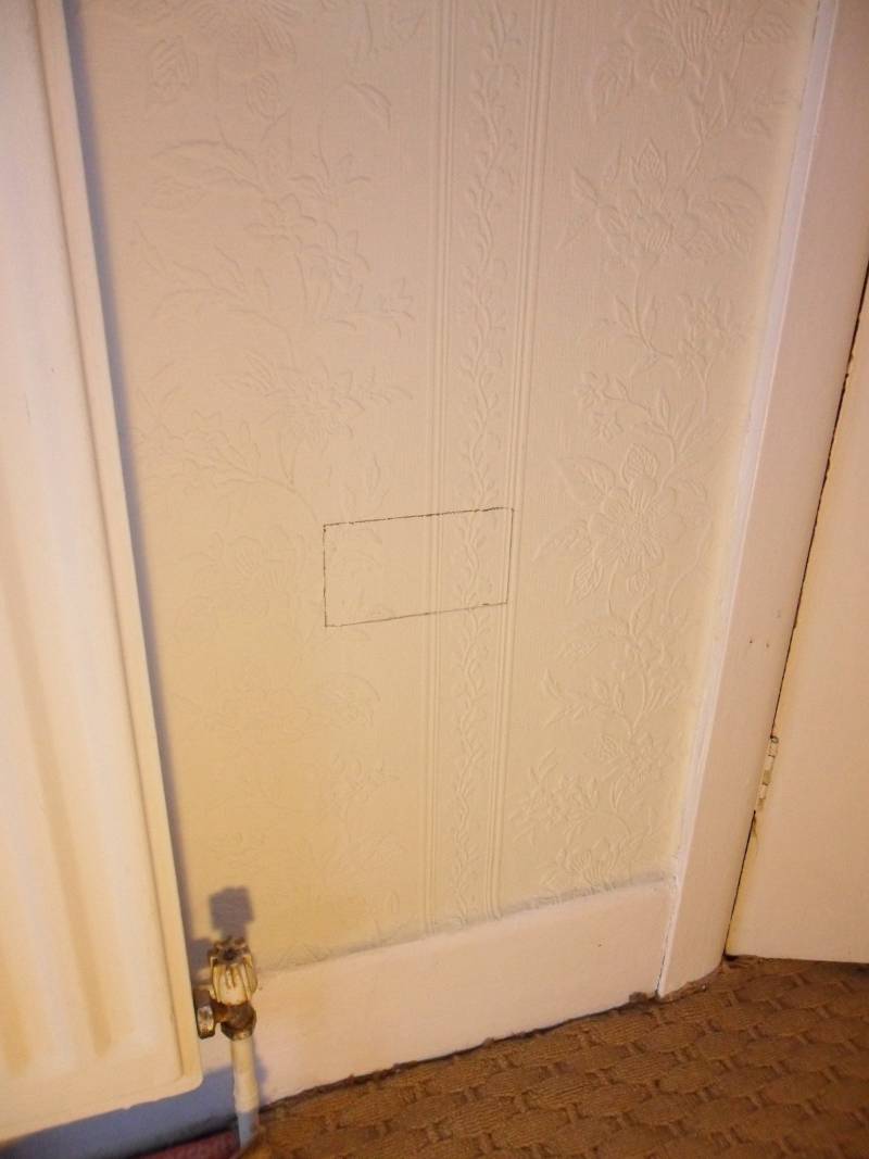
The "Before" picture - a 13A single socket mounted on the skirting board.
DO NOT COPY WITHOUT DETAILED KNOWLEDGE OF THE DANGERS INVOLVED & CORRECT WORKING PRACTICES !
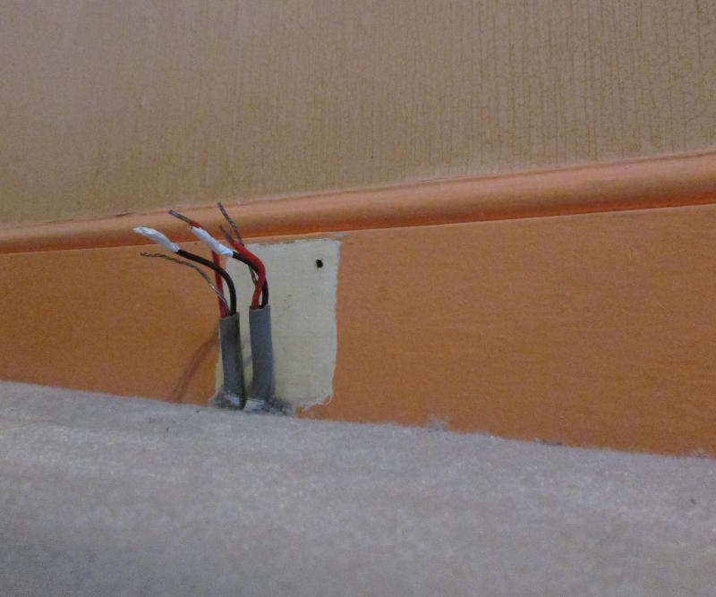
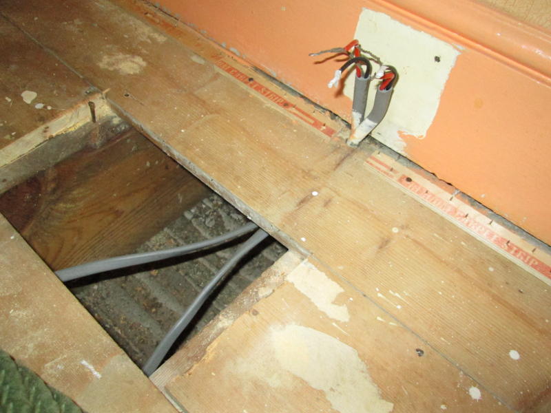
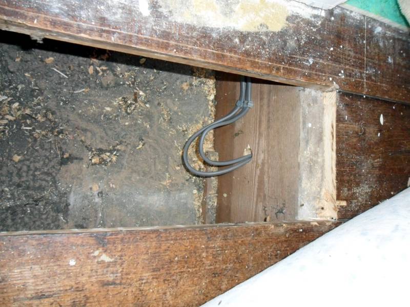
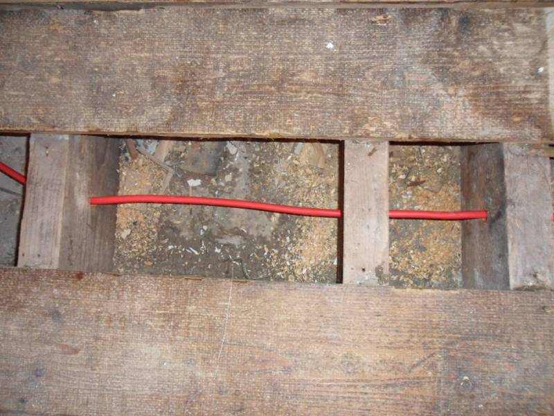
The 13A socket removed, leaving the ring in and out the cables exposed.
In some cases, the cables enter the socket via a hole in the skirting board
rather than through the floorboards & carpet as in this case.
DO NOT COPY WITHOUT DETAILED KNOWLEDGE OF THE DANGERS INVOLVED & CORRECT WORKING PRACTICES !
The cables feeding the socket are too short to reach the new socket position and need extending.
DO NOT COPY WITHOUT DETAILED KNOWLEDGE OF THE DANGERS INVOLVED & CORRECT WORKING PRACTICES !
Marking out the position of the new double socket.
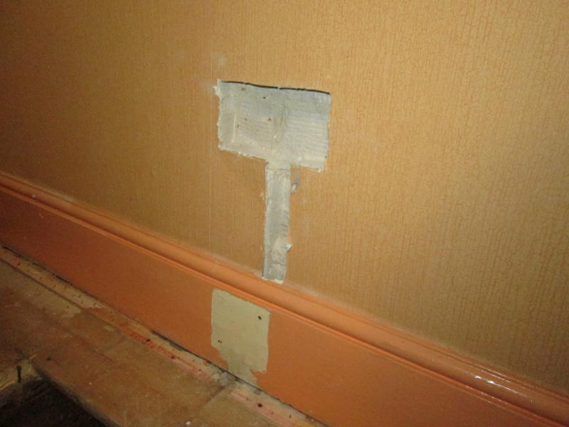
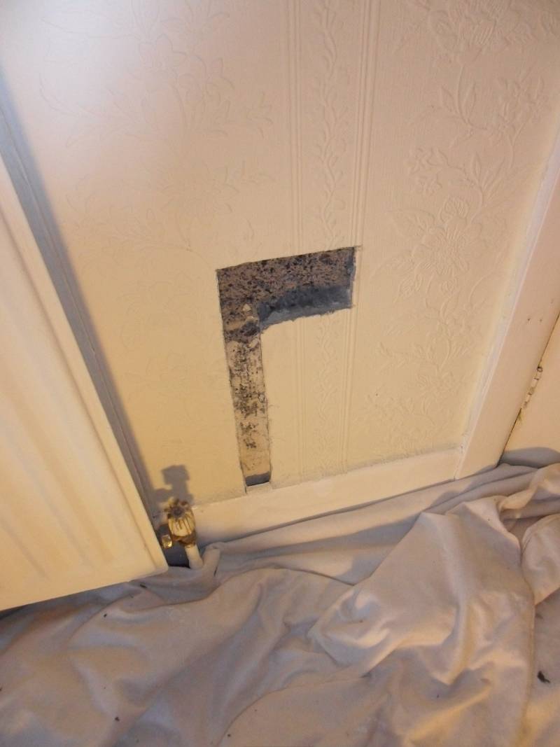
Cutting out the position of the new double socket and chases for the cables.
Like an iceberg, the bulk of the workings for the new socket are below the surface.
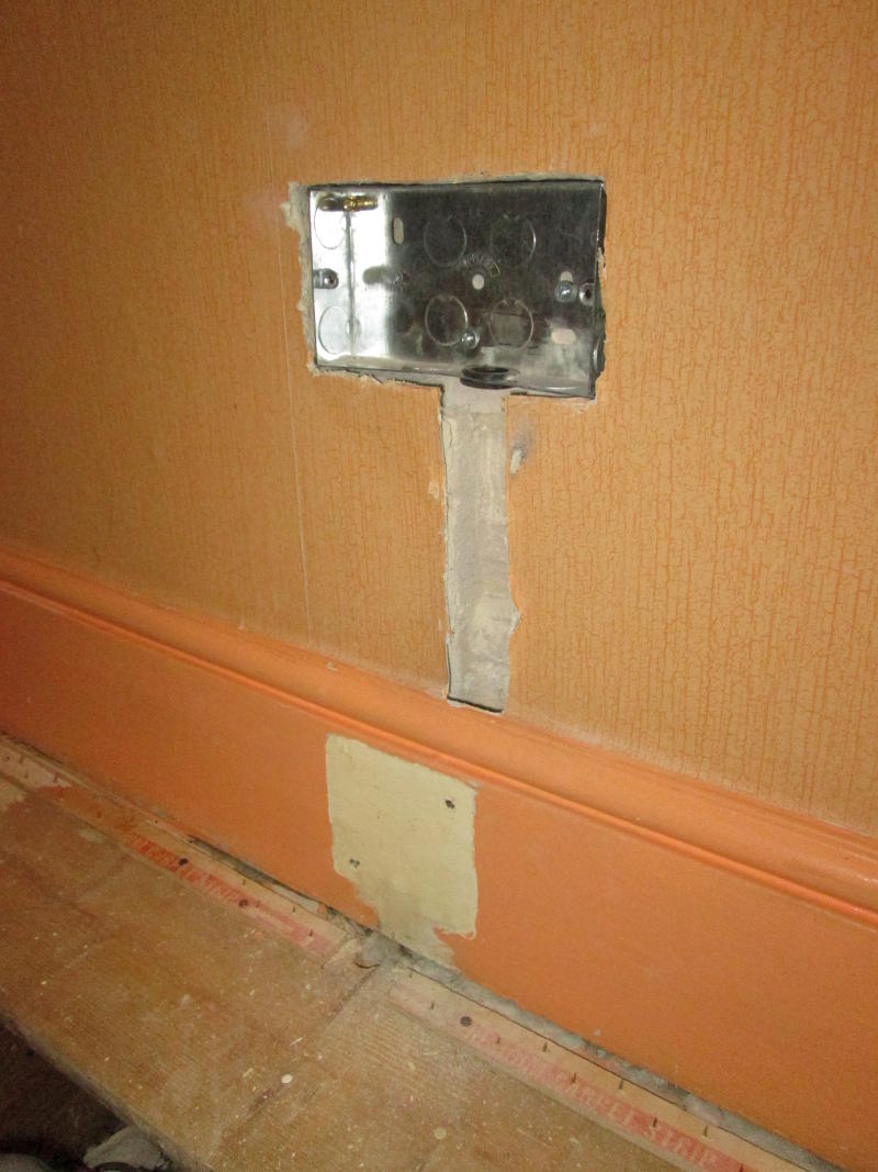
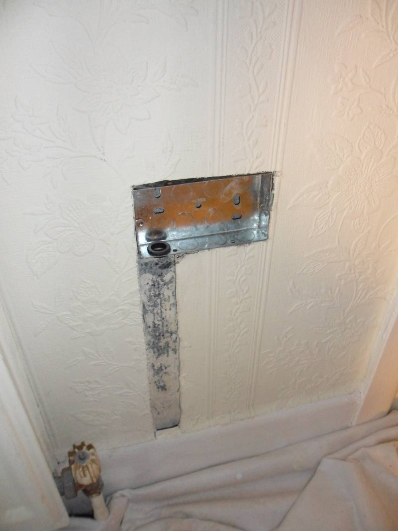
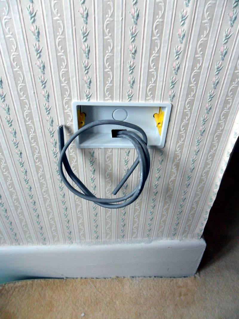
The galvanised backbox (pattress) in place, ready for mounting the new socket.
DO NOT COPY WITHOUT DETAILED KNOWLEDGE OF THE DANGERS INVOLVED & CORRECT WORKING PRACTICES !
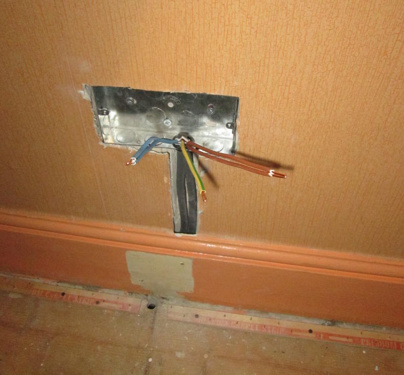
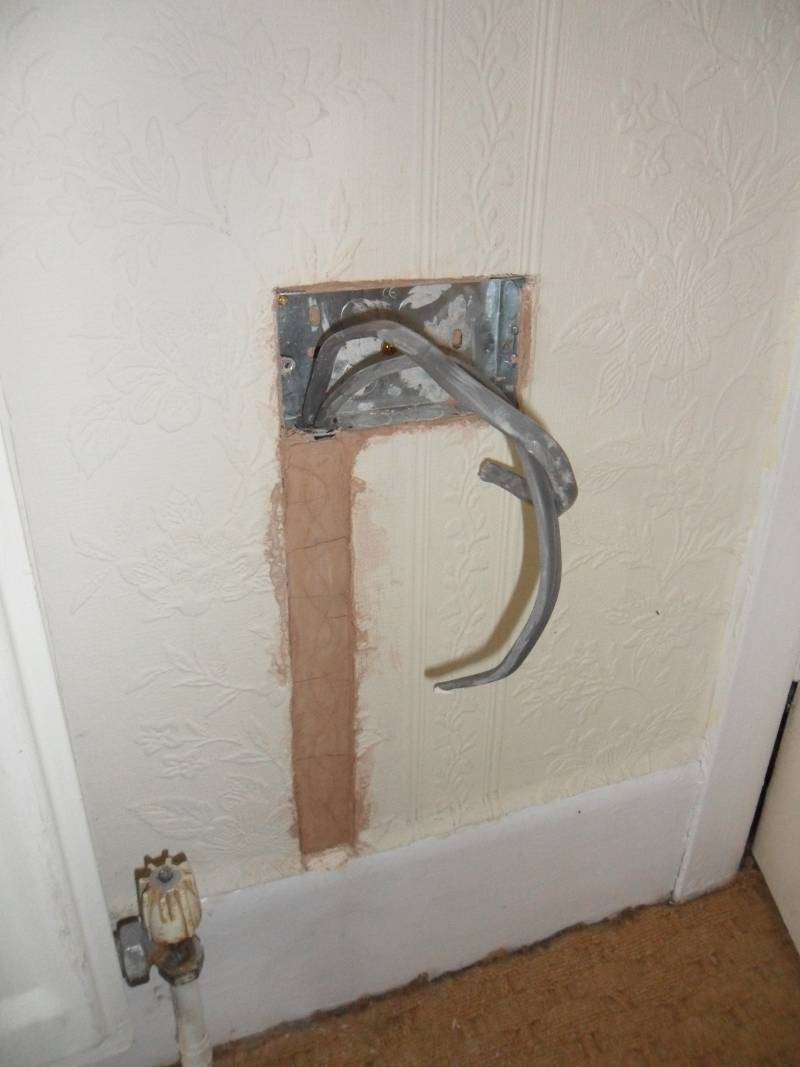
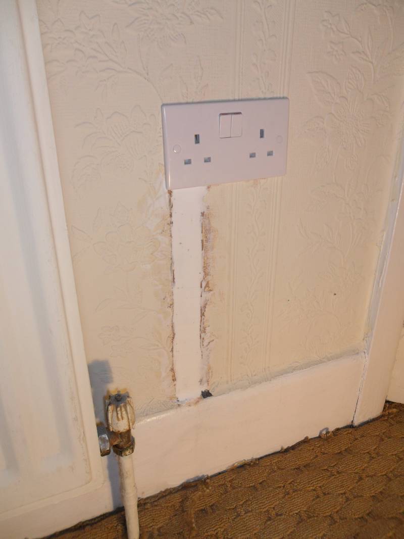
Fitting the extended cabling (later concealed in the wall) for the new double socket.
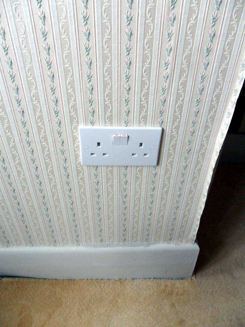
The chase filled to a depth of 2mm below the surface with plaster.
This leaves the work in a state ready for fine filling, sanding and painting or wallpapering.
CASE STUDY 3 - ADDING A WALL LIGHT IN A ROOM WITH COVING
Location:
Eastleigh, Hampshire.
Job Description:
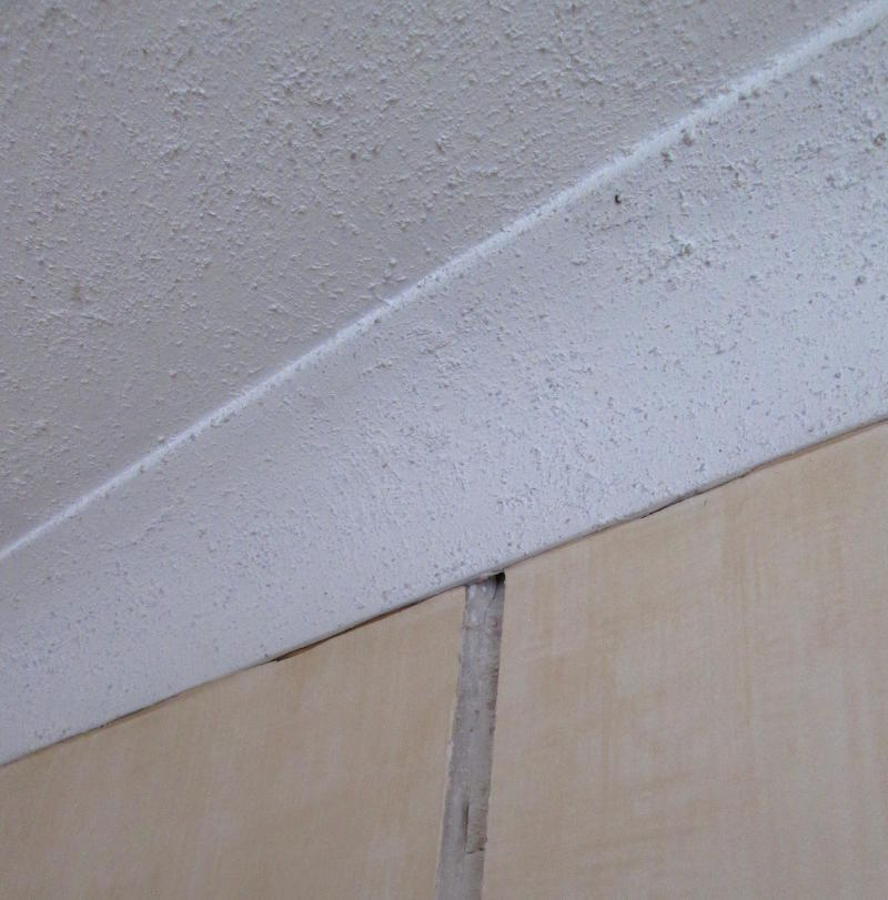
Adding a wall light in a room with coving without damaging the coving and
the cabling for the light concealed in the wall.
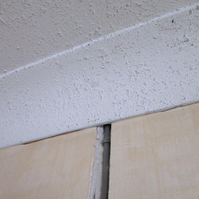
The chase for the cabling in the wall and behind the coving, leading into the loft.
The cabling in the wall, behind the coving and into the loft.
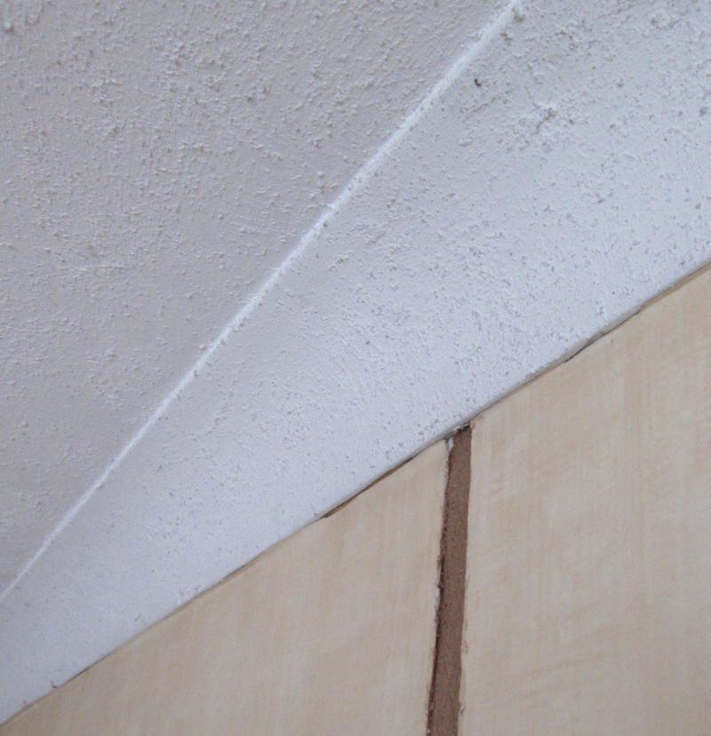
The chase filled to a depth of 2mm below the surface, concealing the cabling.
This leaves the work in a state ready for fine filling, sanding and painting or wallpapering.
CASE STUDY 4 - ADDING A FLUSH SOCKET ON A BRICK OR BLOCK WALL
Location:
Southampton.
Job Description:
This is a typical example of adding a flush mounted 13A double socket
on a brick or block wall.
Marking out the position for the new socket.
Chasing the wall allows room for the cables & backbox for the socket to remain hidden in the wall
when all's done.
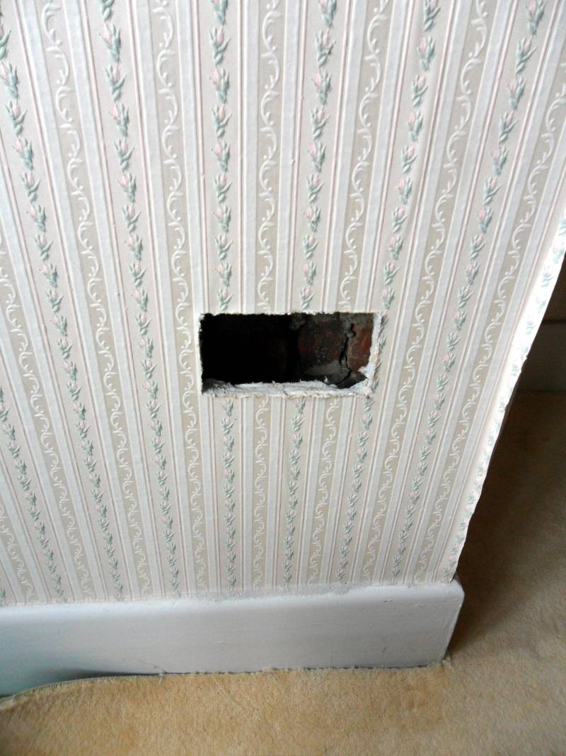
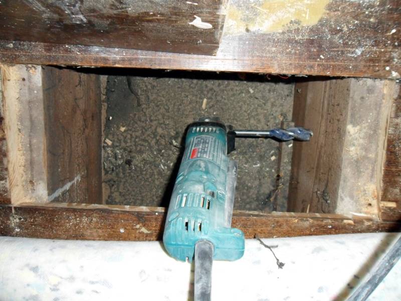
This socket's cabling comes from under the floor, so we use special tools & techniques
to remove material from behind the skirting board to allow the cables through.
Note:
This is not a standard technique and other Electricians will either:
Prise off the skirting board with a crowbar and hammer it back when finished.
Cut out a section of skirting board and glue it back afterwards.
Break off the skirting board and leave it to one side or throw it in the skip.
The backbox (pattress) provides a solid fixing point for the socket.
The black rubber "grommet" fitted at the bottom left protects cables
entering the backbox from damage by the sharp edges of the metal box.
When the cables are routed to the socket, but not connected (first fix),
the chases can be bulk filled (with plaster or a sand/cement mix).
When the socket is wired up (second fix) and ready for testing, the chases can be fine filled.
Once the chase has been fine filled, it's time to decorate.
CASE STUDY 6 - TOTAL REWIRE OF AN OCCUPIED 1950s HOUSE
Location:
Off Hill Lane, Southampton.
Job Description:
The most challenging domestic electrical job is a total rewire when the house is occupied
for the duration of the work. This rewire was needed because the original rubber covered cabling had
degraded to such an extent that there was an immediate risk of fire and electric shock.
This job had the added complication that some of the original 1950s features had to be preserved while
modernising the rest of the house.
There seems to be a revival in 1950s styling at the moment and we have been involved in several restoration projects of this type.
The other galleries show examples of our completed works, but this one shows the major steps involved in getting from start to finish (apart from final decoration) of a complete rewire, where everything has been done properly by us (the only way we do it).
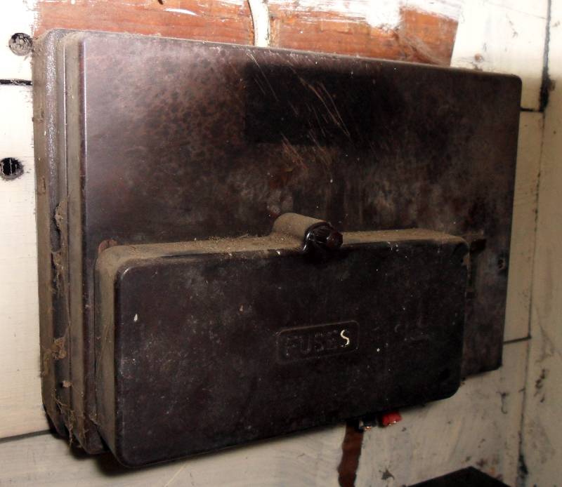
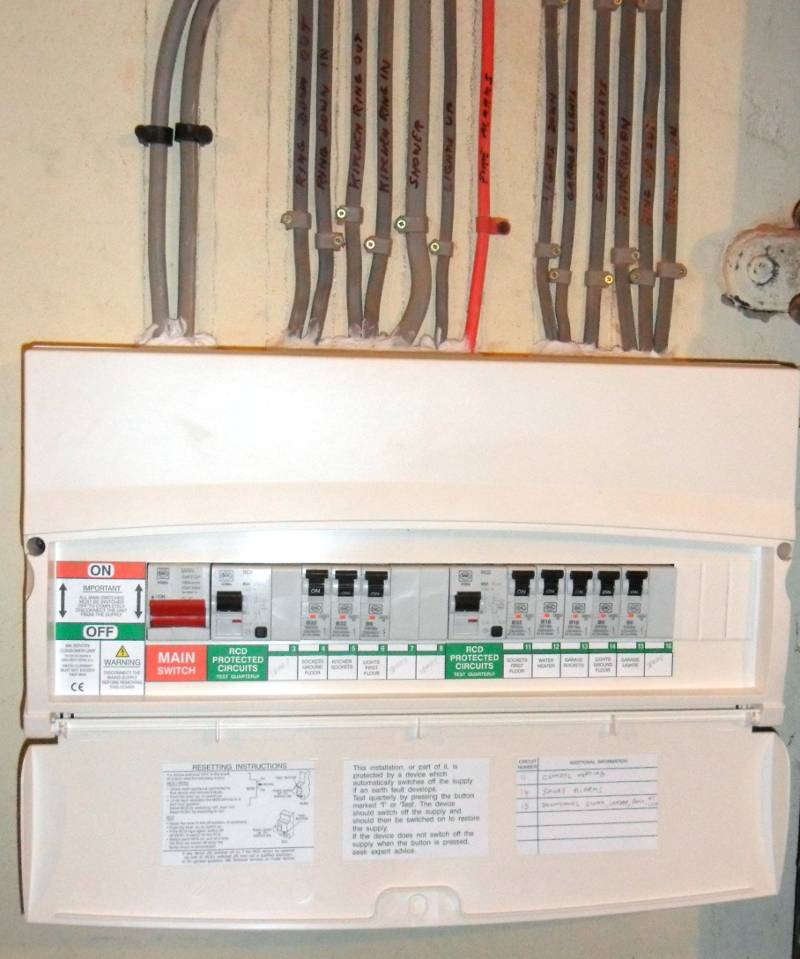
The "Before" picture - of an original 1950s fusebox.
When it was installed, rubber covered cables were used throughout the house.
Over the years the cables had perished and were in a very unsafe state.
The fusebox itself has an open frame, made of wood (a fire risk in itself) and a Bakelite cover.
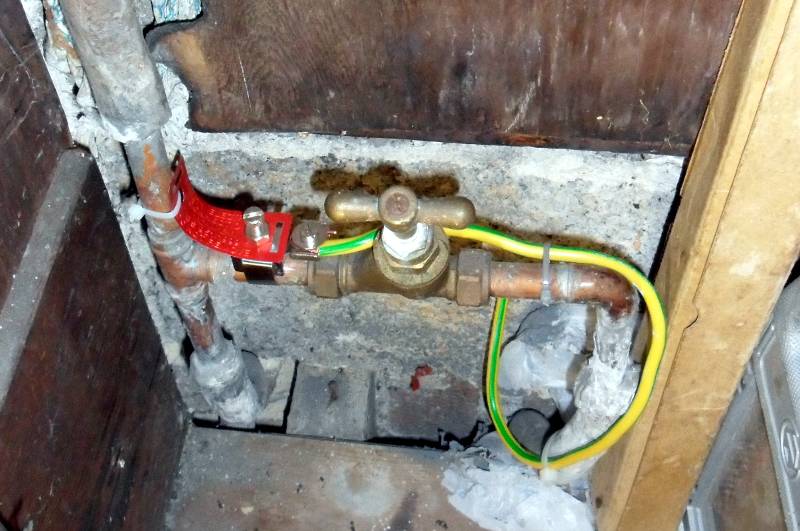
A major requirement of the wiring regulations is that the water & gas supplies to the property are connected (bonded)
to earth where the supply enters the property with 10mm green/yellow cable (about the same diameter as a normal pencil).
The reason being that if a fault occurs where the water or gas pipes in the house become live - eg from a faulty electric shower
or gas boiler, all the metal pipes are connected to earth and there is reduced risk of an electric shock.
Modern Water & Gas main supplies in the street use plastic pipes, so there is no guarantee that they form a connection
to earth unless we provide one.
For the same reason, it is no longer acceptable to use a connection to the water main as a means of earthing for the property
as was the case until the mid 1960s.
The wiring regulations insist that earth bonding is in place before any other electrical work is undertaken.
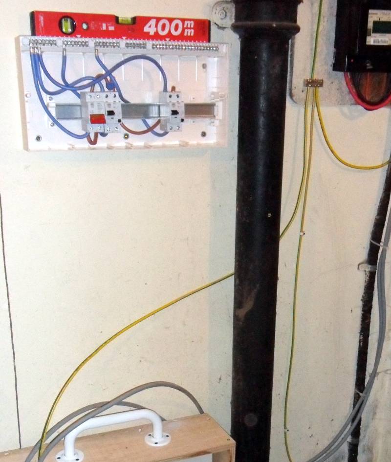
The finished main bonding to the water main.
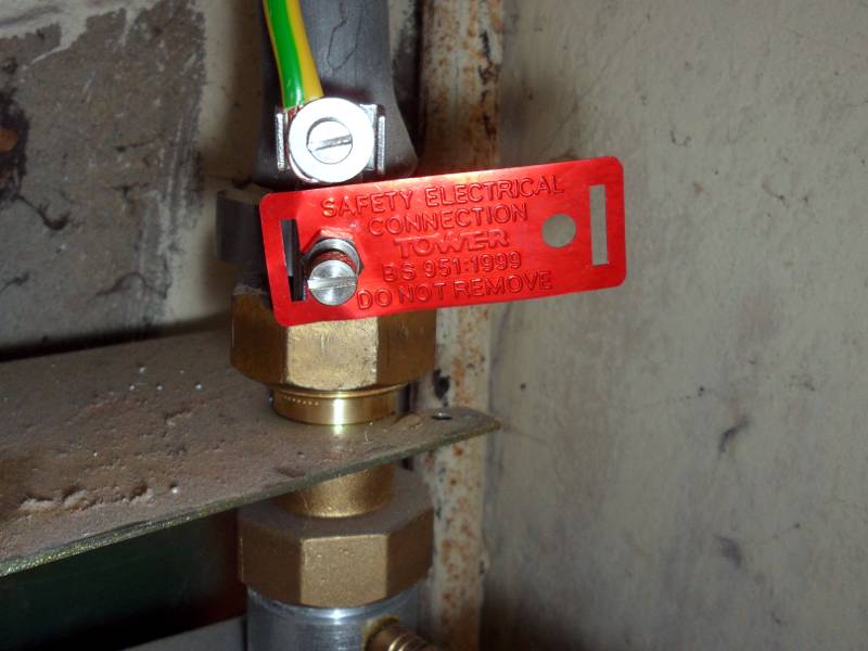
Another requirement is that the connection to the pipe is via a BS951 bonding clamp with a label marked:
"Safety Electrical Connection - Do not remove".
Similarly, the finished main bonding to the gas main.
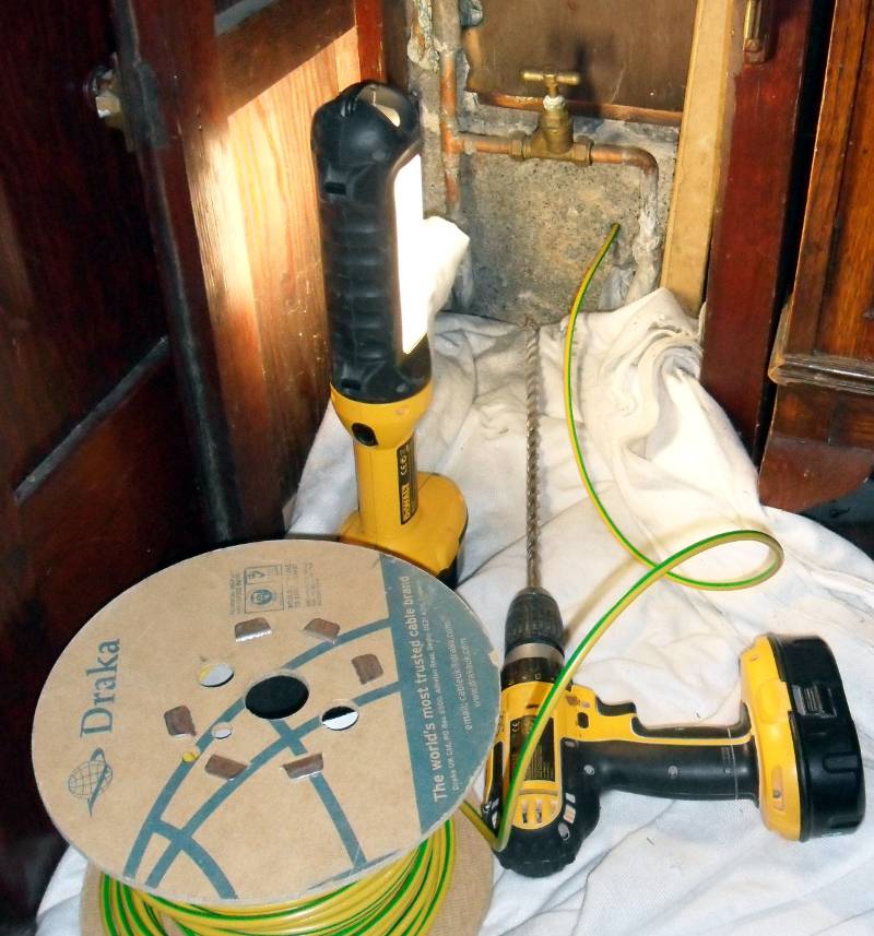
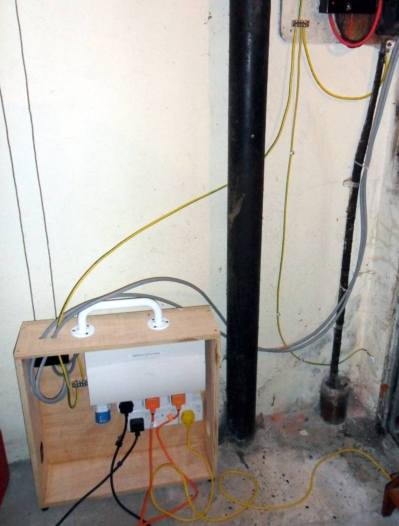
Now that the main earth bonding is in place, we can install a temporary consumer unit (on the floor in a wooden enclosure),
so we can keep essential electrical equipment running while the work is done.
By essential equipment we mean - lights, fridge/freezer, Microwave Oven, central heating, TV, Computers etc.
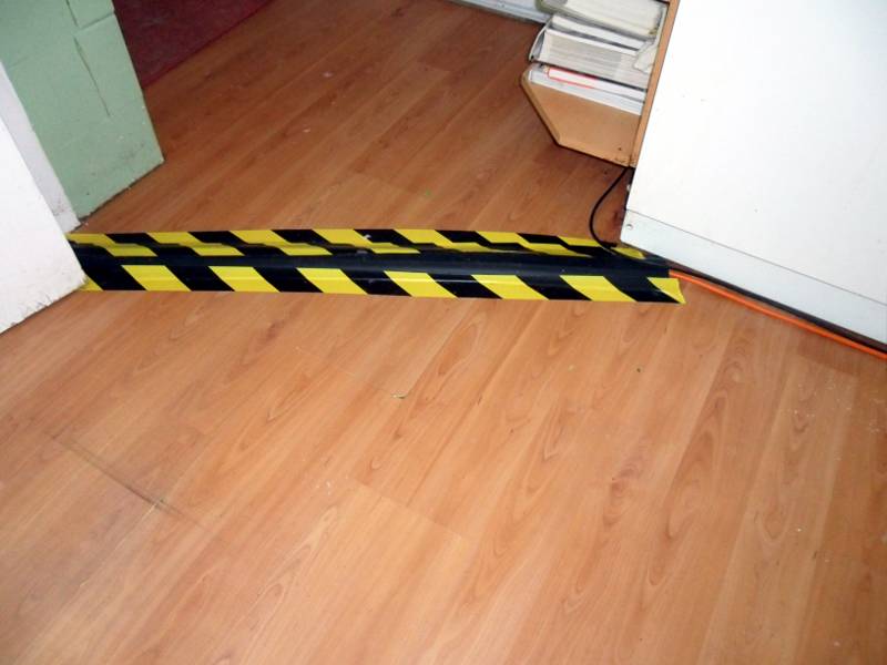
The temporary cables run in special heavy duty rubber coverings in walkways, like here in the kitchen.
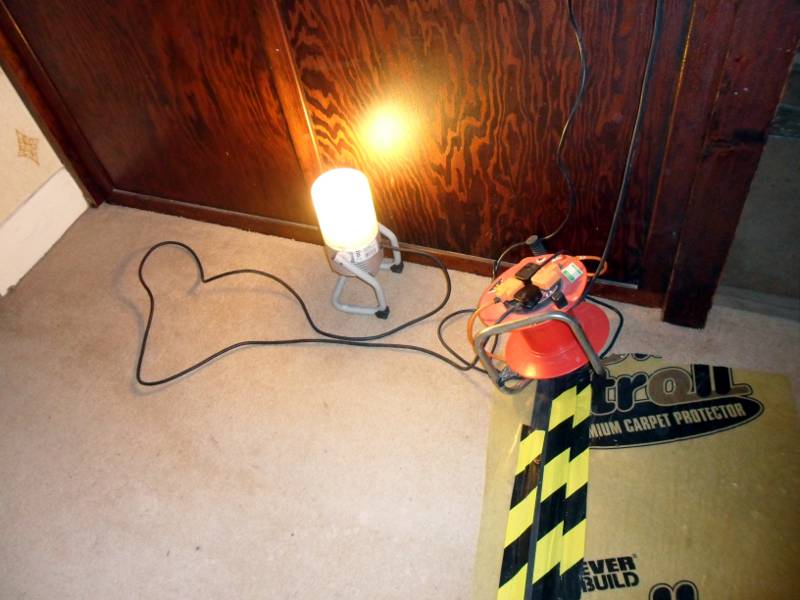
For general purpose room and hallway lights, we use this type of light.
This light is about to be re-positioned so as to give stairwell lighting.
Now that the essentials are up and running (and the kettle works again), we can start removing the old fusebox
and wiring, and start fitting the new consumer unit (at a height that doesn't need you to stand on a chair to reach it).
Now that it's safe to touch the old wiring without setting fire to the house, we can get started.
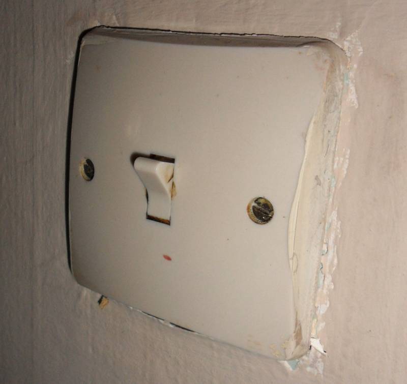
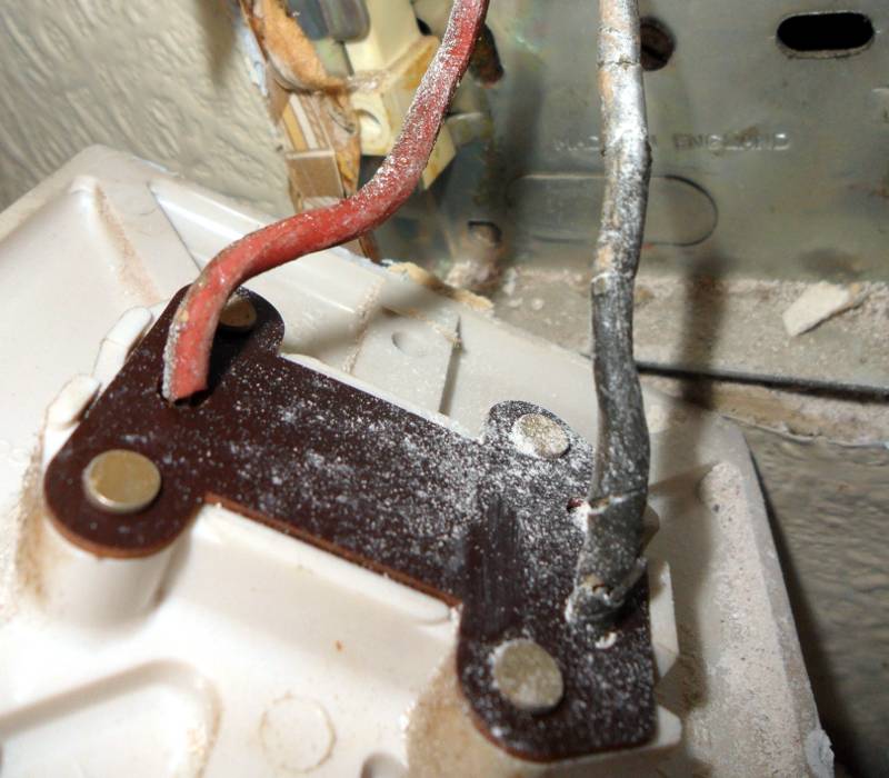
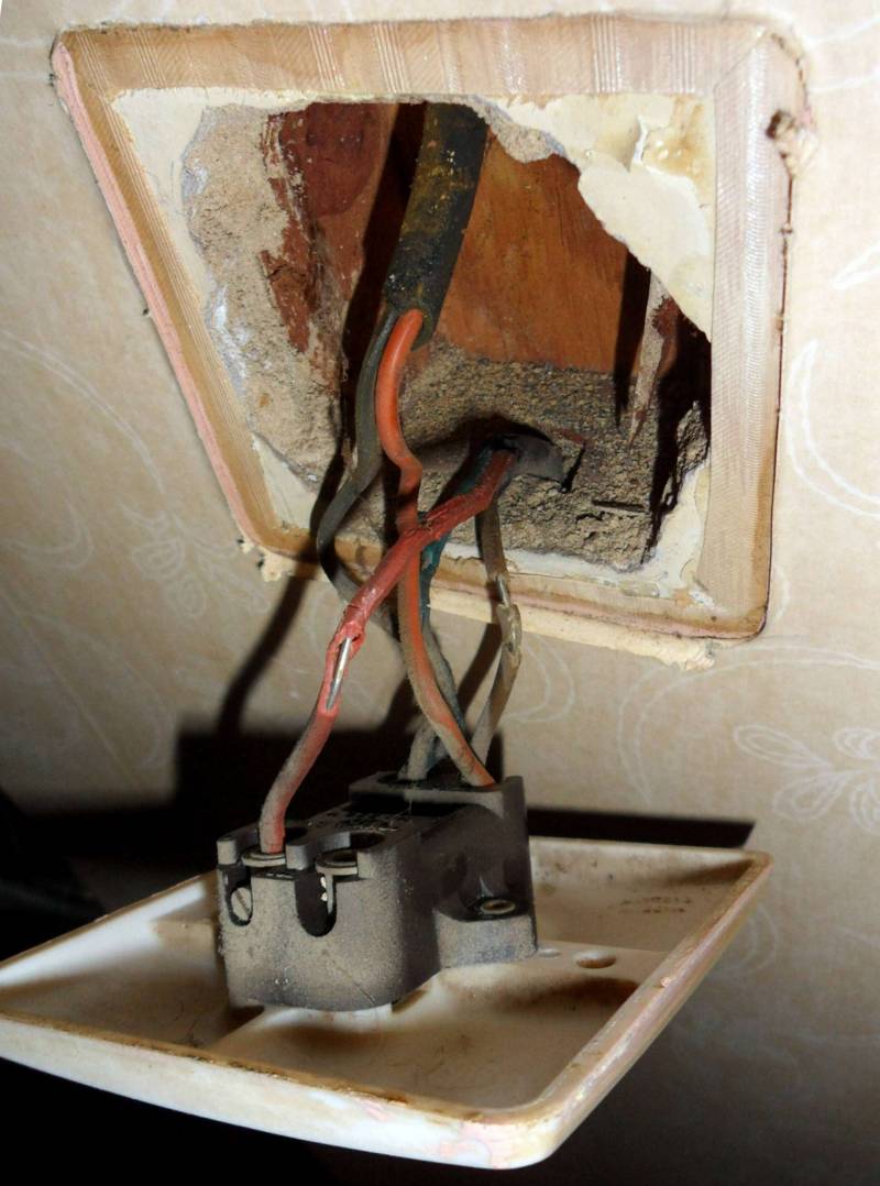
This original 1950s light switch has seen better days, but on the surface of it looks ok.
But once it's removed, it's obvious that the rubber insulation covering the cable has perished.
Another type of rubber insulation failure, this time from another 1950s restoration where
the insulation crumbles away in hard flakes when disturbed, exposing the live wires.
Note the wooden backbox for the light switch - this is typical of 1950s electrics.
Also - note that there is no earth connection in the cabling for the switch, which is typical
of lighting circuits installed before the mid 1960s.
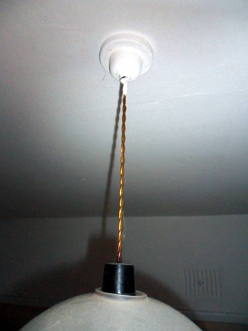
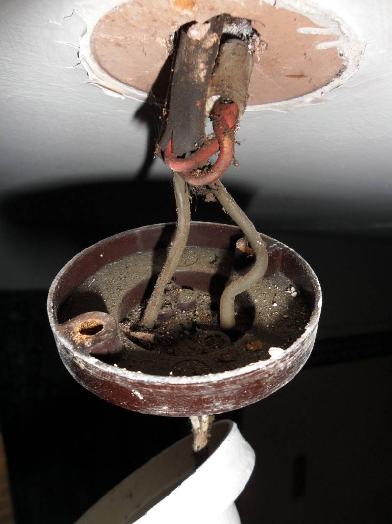
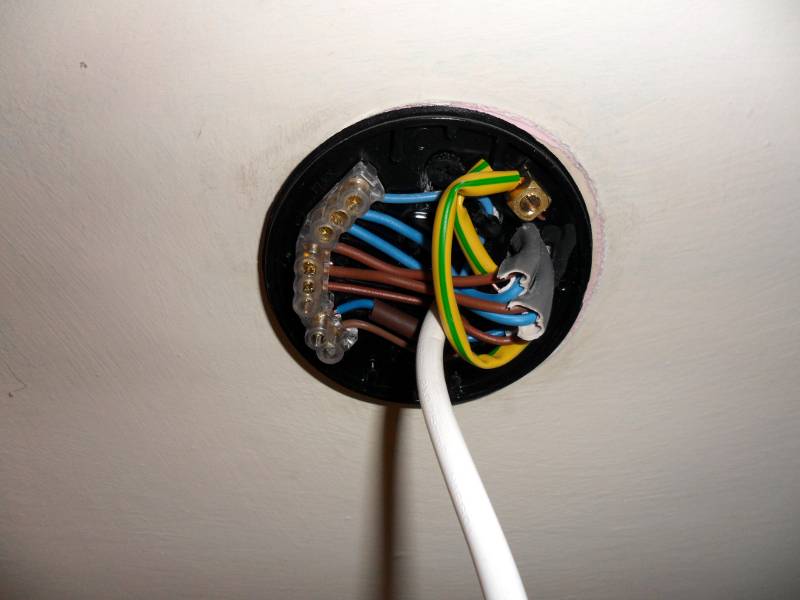
As with the light switch, this original 1950s pendant, complete with twisted nylon flex
and brown Bakelite lampholder, has seen better days but looks ok at first sight.
Once dismantled, the rubber insulated cables can be seen and again no earth connection.
The two red wires are twisted together and capped with a "scruit" - no longer acceptable as a means of making an electrical connection.
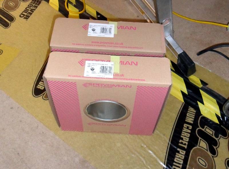
We only use good quality, branded and BASEC approved cable for all our work.
This "Prysmian" cable (the company formally known as "Pirelli") comes from a local source.
If the original cabling ran in conduit buried in the wall, it's usually possible to use it for the new cables.
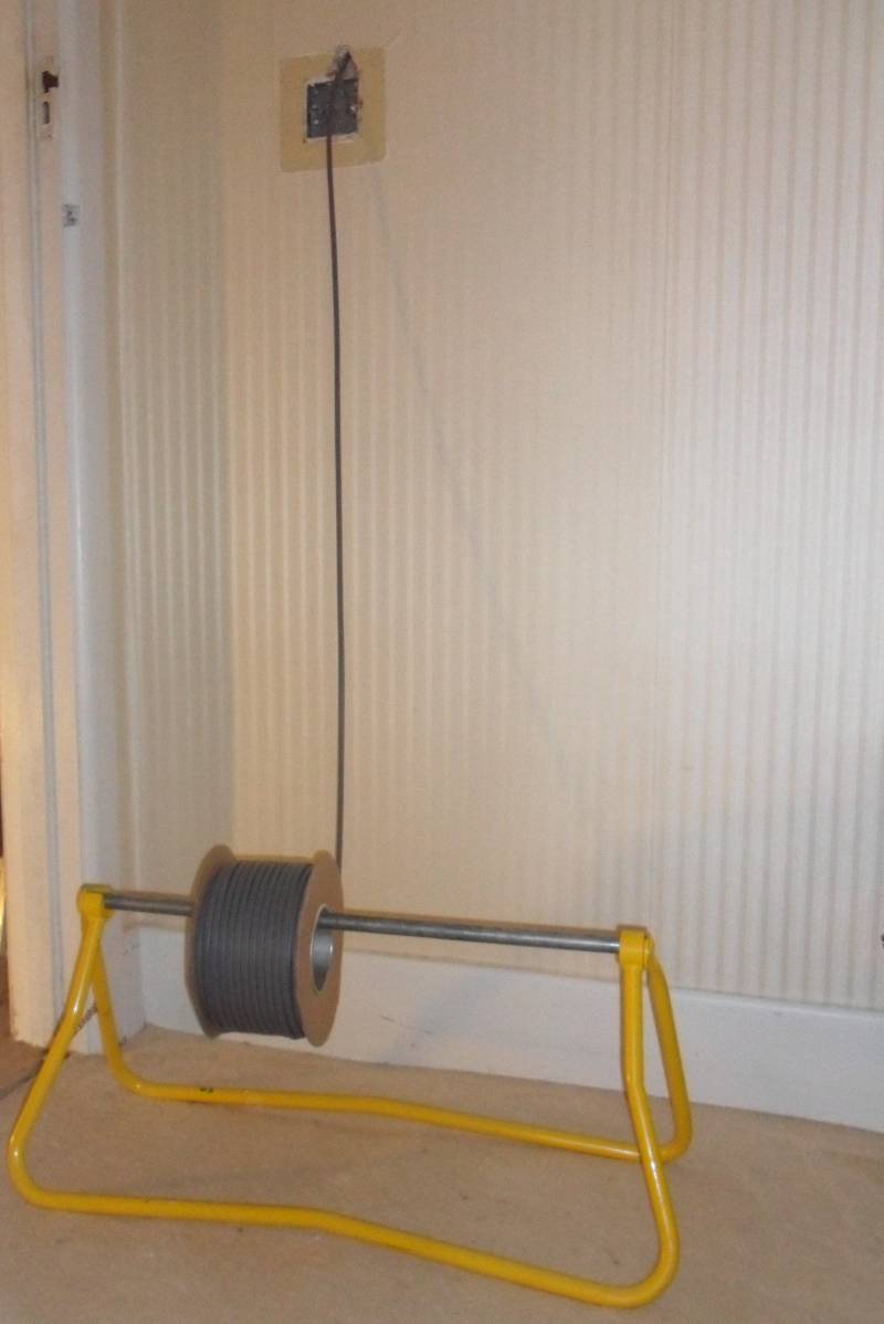
A cable cradle like this one prevents the cable twisting while on route.
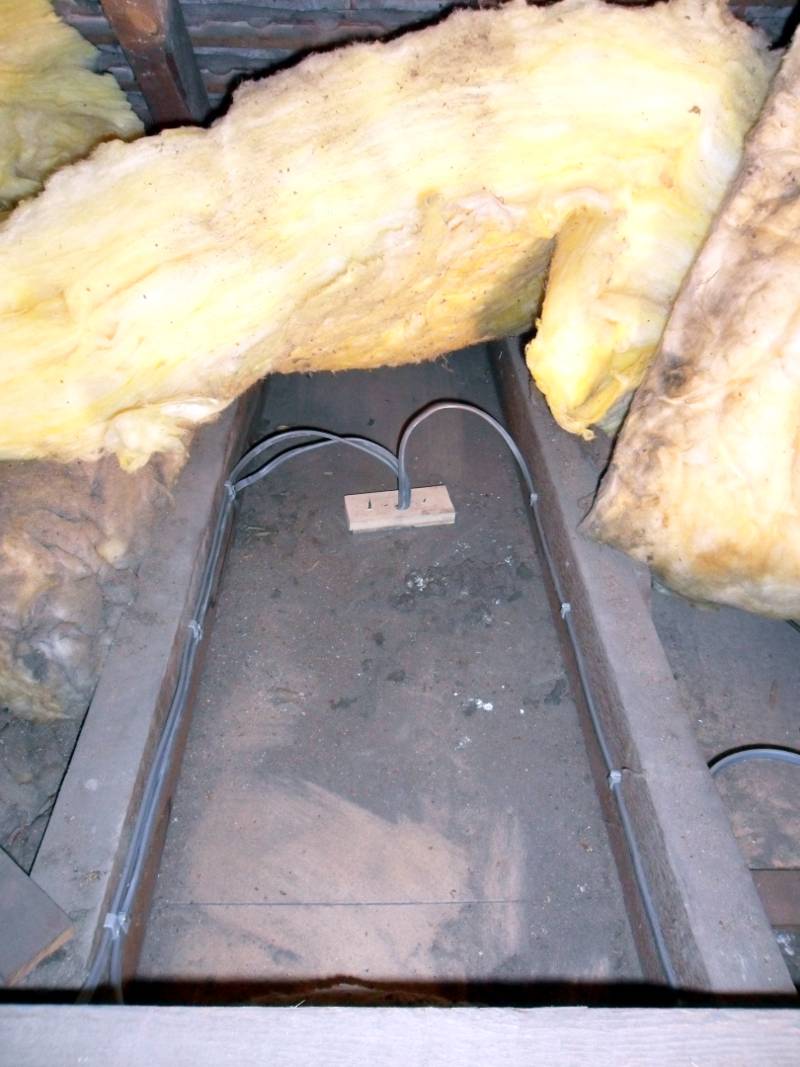
The new lighting circuit wiring, neatly clipped in the loft.
The new light pendant wiring with earth sleeving & brown sleeving on the blue switched live wire.
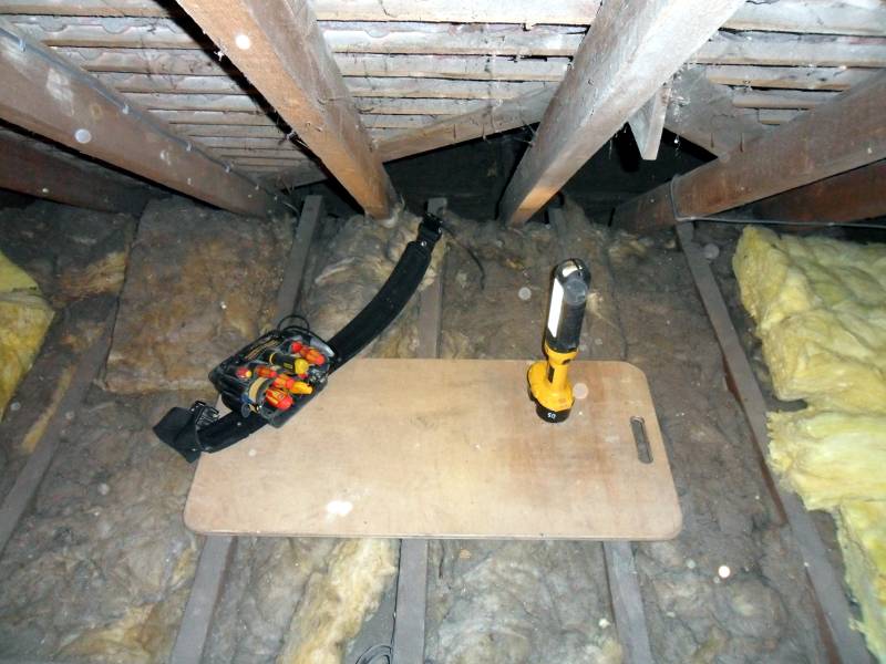
Working in the loft can be dangerous, so we need to take extra care when there.
We use "crawler boards" to support our weight when working in the loft.
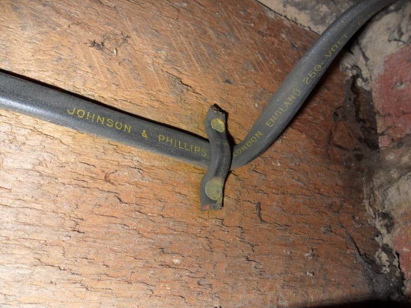
Old rubber insulated cable in the loft looks like this.
Note the "old school" method of clipping the cables to the joists (only used by rogues today).
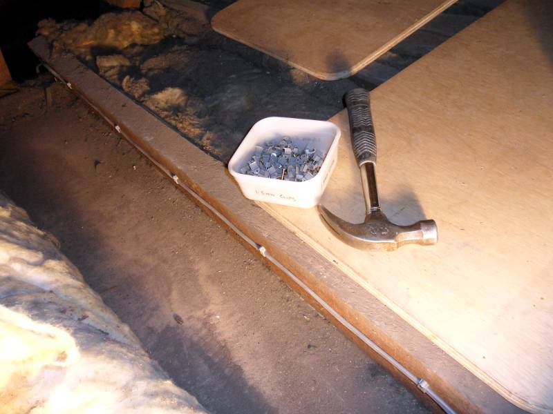
Cables need to clipped to joists at intervals specified in the Wiring Regulations.
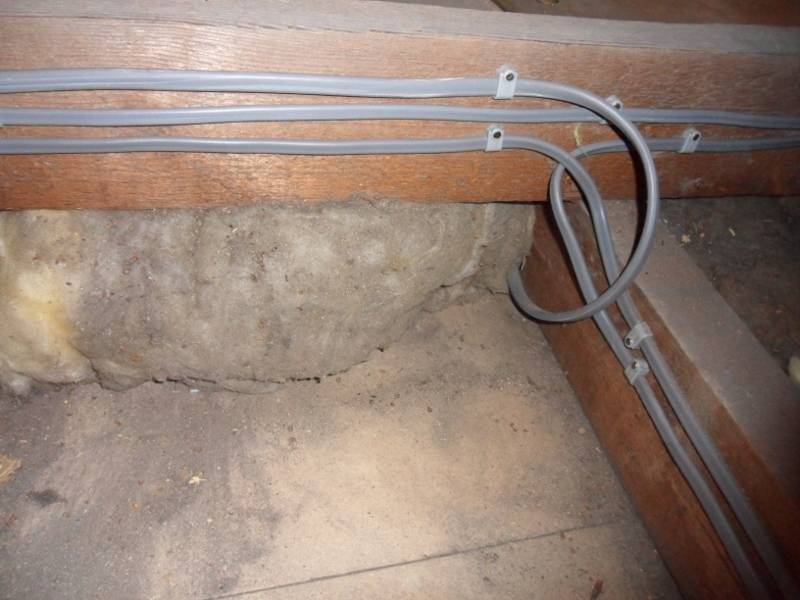
We clip the cables to the side of the joists where possible so the loft can be boarded over at a later stage if requires.
Groups of cables should run neatly together.
There's two schools of thought on what to do when the cable runs change direction.
(1) Clip the cables tightly into the corners.
(2) Leave some slack to allow for movement and a convenient place for a junction box if required at a later date.
We normally go with option (2) unless there is a good reason to go with option (1).
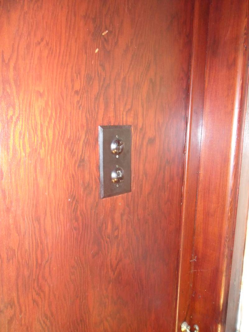
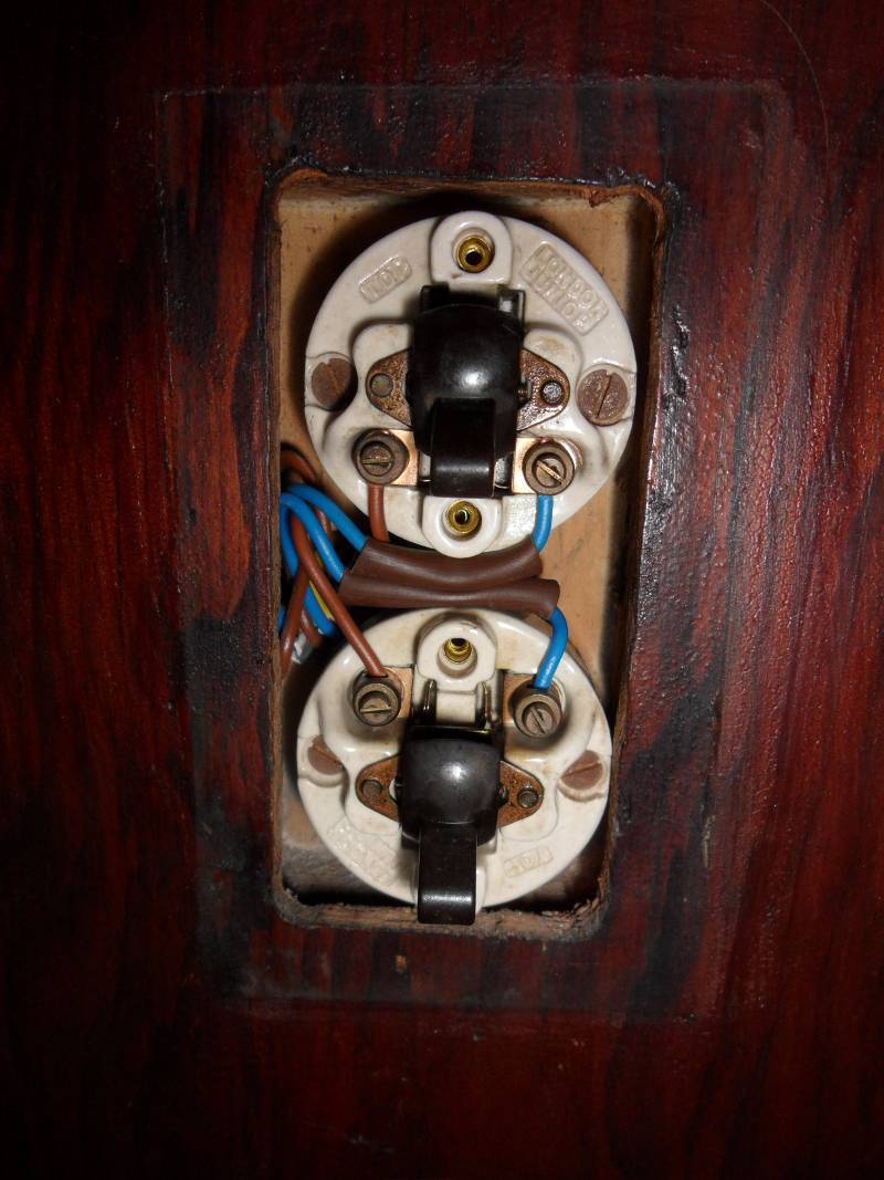
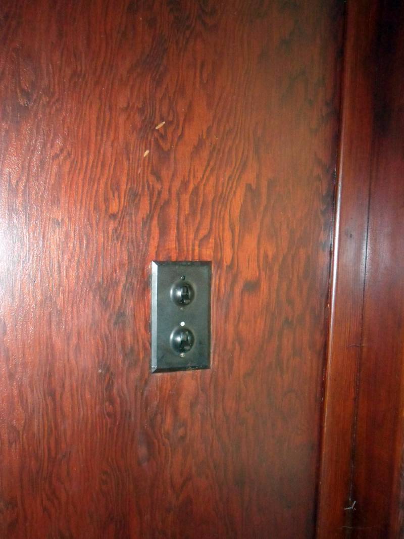
Now to one of the interesting parts of the project - this "Lincoln style" double switch needs to be rewired
without damaging the lacquered wooden panelling it's mounted on and the panelling covers the entire entrance hall.
There's another "Lincoln style" single switch in need of the same treatment at the other end of the hall.
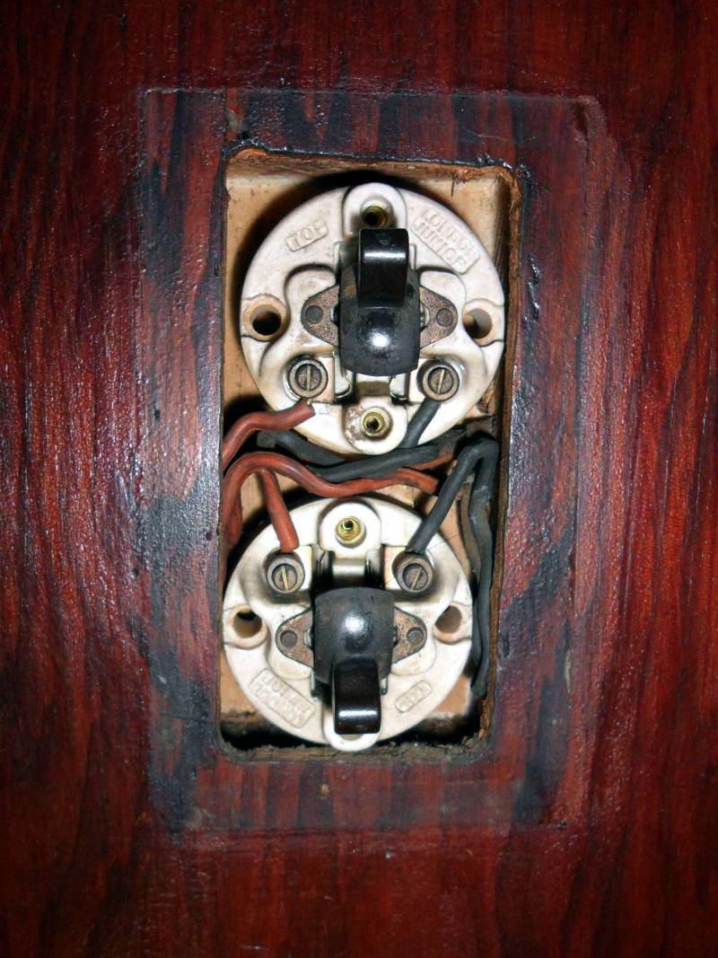
The "Lincoln style" double switch faceplate removed, showing two individual switches
and original rubber insulated cables without an earth.
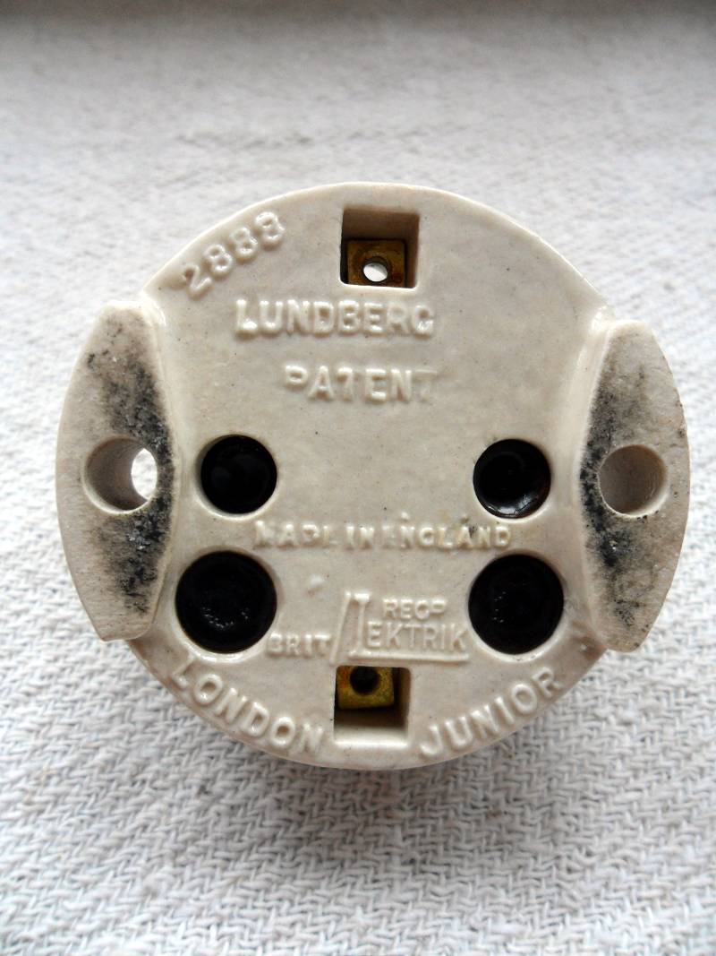
The base of one of the "Lincoln style" switches, showing that it was made by Lektrik Ltd.
The "Lincoln style" double switch rewired, refitted and tested in place before fitting
the fireproof base and final assembly.
The "Lincoln style" double switch, back in place & working.
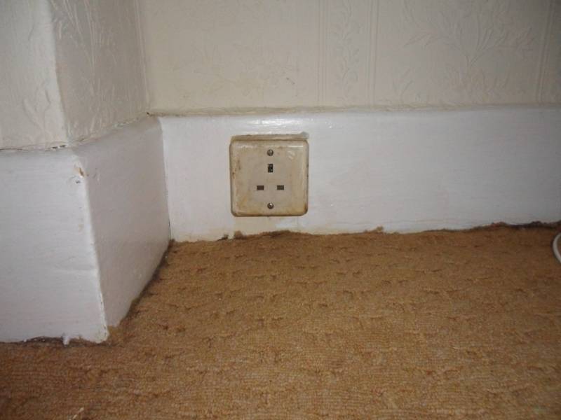
Typical of 1950s houses, there's not enough sockets and they are fixed to the skirting board.
Note the top and bottom mounting screws on the socket - modern sockets have the mounting screws on either side.
For new builds, sockets have to be at least 450mm from floor level.
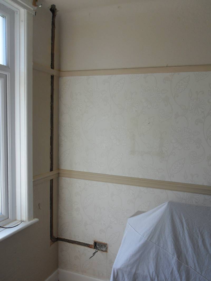
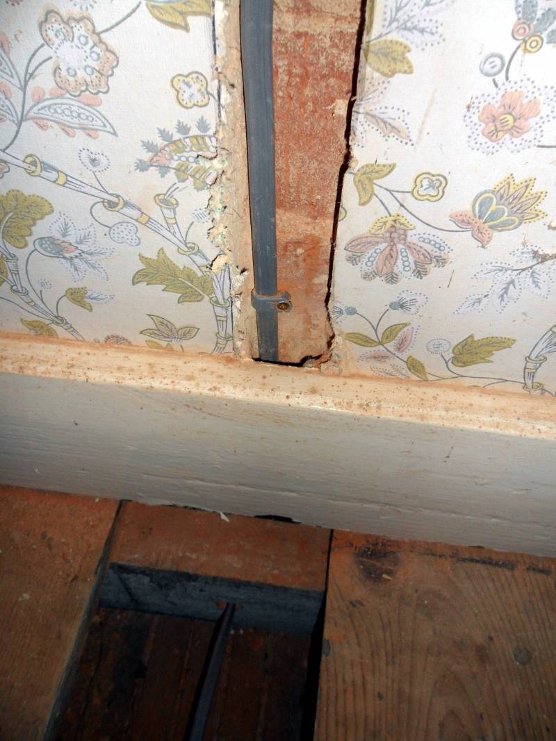
There's a parquet floor in this downstairs room, so the cable runs to the sockets have to come from above rather than below.
We have developed special techniques to preserve features like skirting boards, dado rails, picture rails and coving
for restoration work. Here is a typical example of cabling past a picture rail and dado rail while rewiring
without causing any damage to the original features.
Note: The Wiring Regulations only allow cables to run in "Safe Zones" - horizontally and vertically from sockets & switches, near the top of a wall at the ceiling and at the corner junction of two walls as in this case.
Another example of routing cables in chases without removing or damaging the skirting board.
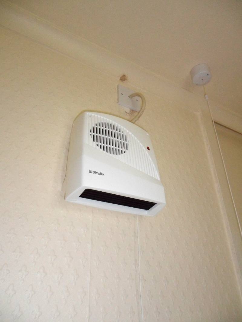
Here we fitted a fan heater suitable for the bathroom.
The pull cord switches the fan on and off, but a double pole isolator must also be fitted.
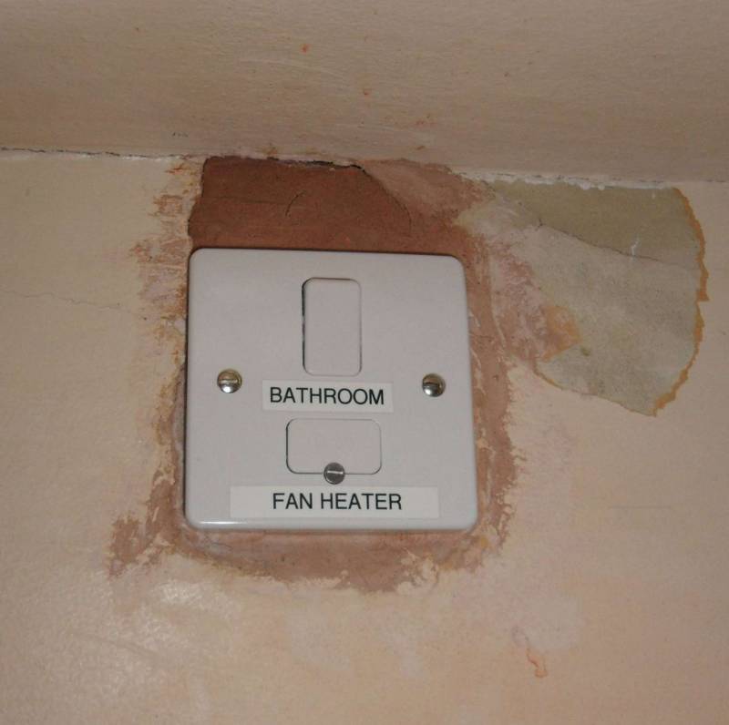
The Wiring Regulations do not permit normal switches (or fused spurs - like this one)
to be fitted in a bathroom, so this fused spur is fitted outside the bathroom door.
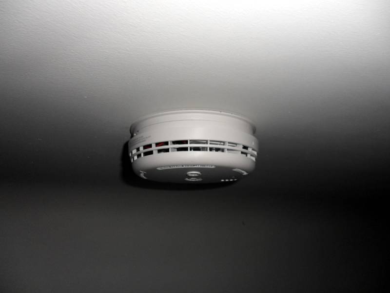
Here we fitted a ceiling mounted mains powered with battery backup smoke alarm.
Other smoke alarms were fitted throughout the house and a heat alarm in the kitchen.
All the alarms were interlinked, so if one triggered, they all alarmed (as per the BS5839-6 specification).
Fire alarm cabling must take a different route than that of normal mains cable and
for commercial fire alarms, should be in fire retardant cable (e.g. FP200 cable).
We normally use FP200 for domestic fire alarm cabling unless instructed otherwise.
The new consumer unit, cabled up and ready for testing.
Once complete, the cables will be boxed in and not visible.
This is a very short sequence of the major steps required to complete this job.
TRADE SECRETS
To access the "Trade Secrets" page,
please
contact EEC
for the password: