eec247 Homepage

COMPACT FLUORESCENT LIGHTING


Home Gallery Emergency Help Contact Us

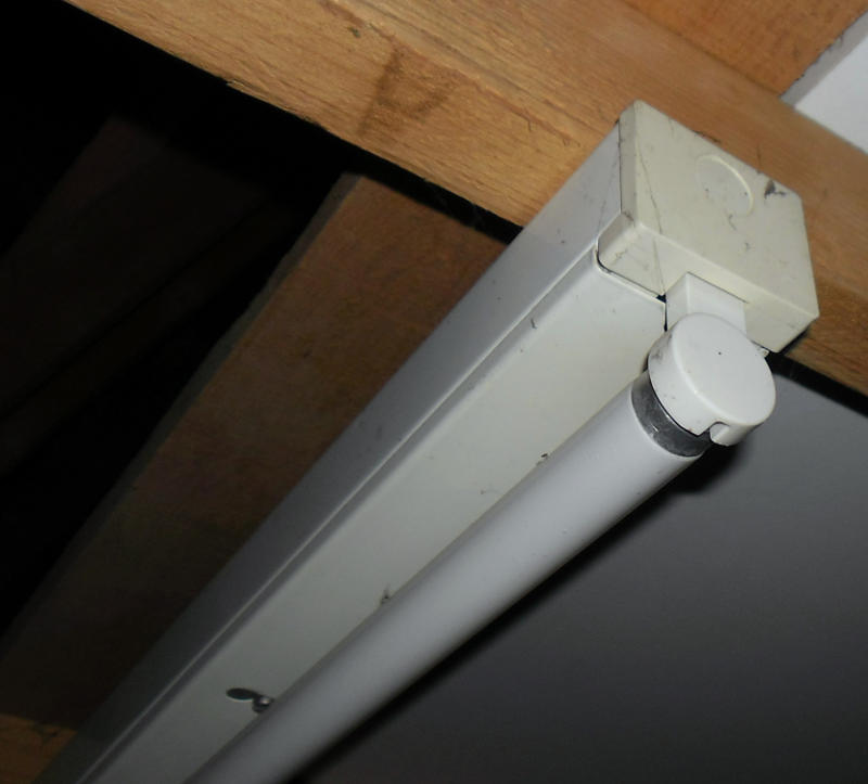
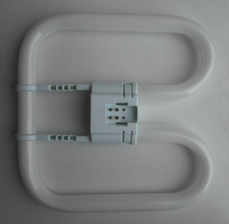
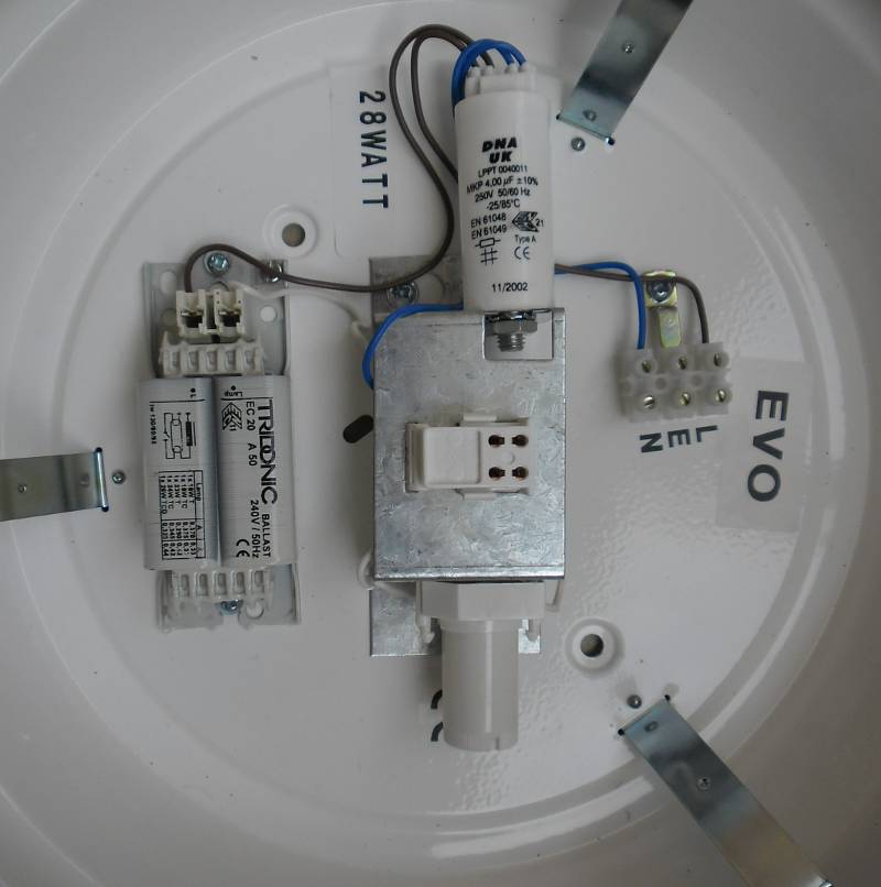
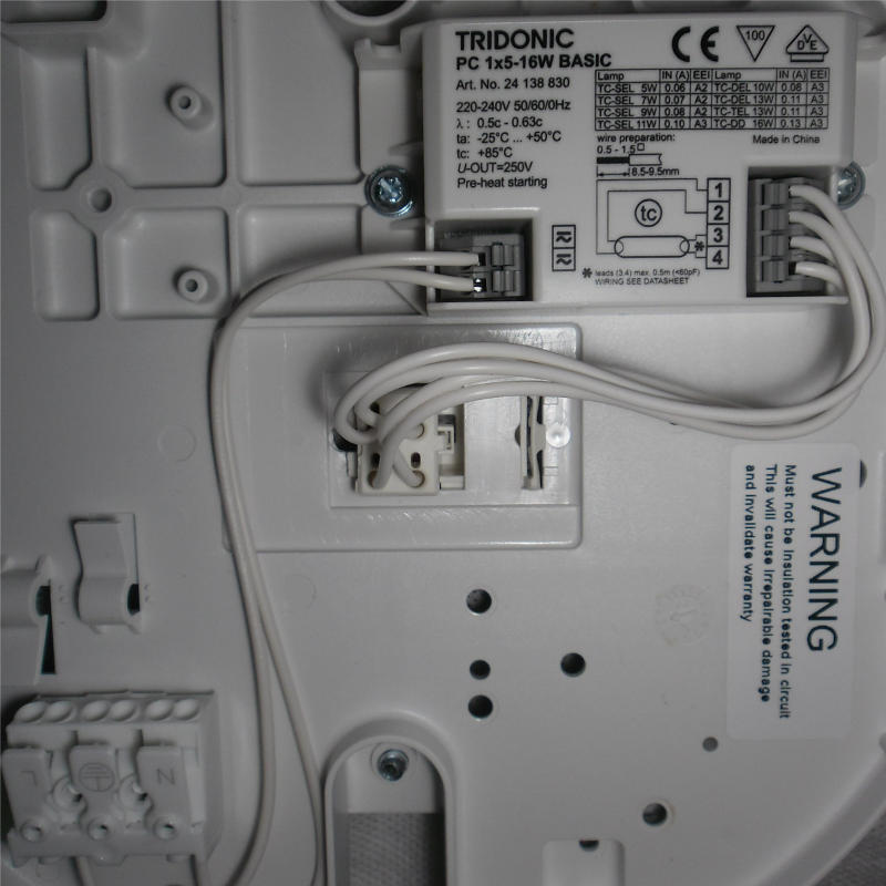
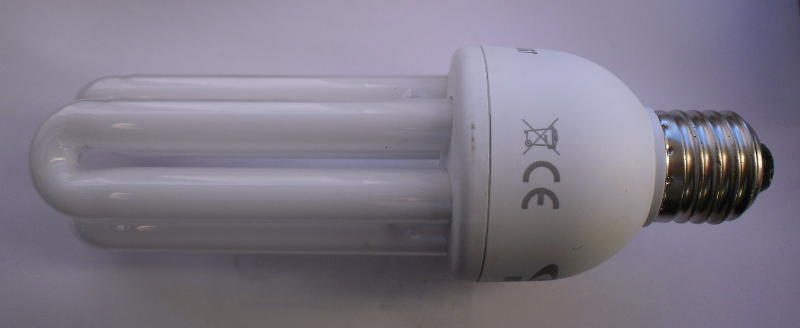
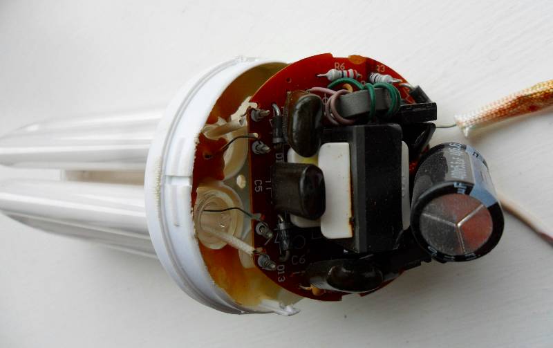
Compact Fluorescent Lamps (CFLs) have their origins in Fluorescent lights - just like long strip lights
used in offices, shops, factories and schools for nearly 100 years.

Do not break open old Fluorescent tubes or CFLs - they contain material that can make you very unwell.


#
Neon capsule - unpowered and powered up

In the late 1600s and early 1700s, Scientists found that passing an electrical current through some gasses
sealed in glass tubes at low pressure caused the gas to give off light or Fluoresce.

The simplest example of this type of device in modern use is the "Neon" found in many household appliances
and as an indicator in some sockets & switches around the home (the cooker switch usually has one).

The photograph above shows such a "Neon" indicator in it's raw form. Before the electric current is applied,
the electrodes are clearly shown inside the glass tube. When an electric current is applied, one of the electrodes
glows with a distinctive Orange/Red hue, typical of Neon Indicators & Neon Signs.

#
photograph of a typical Fluorescent light fitting

Here is a typical Fluorescent light fitting.
Fluorescent tubes of this type need the gas inside the tube to be warm before the gas will fluoresce.
In fact, the light produced is not visible - it is in the Ultra Violet part of the spectrum.
The inside of the glass tube is coated with a cocktail of phosphorus materials that glow white when subjected
to the energy of the Ultra Violet light produced by the electric current flowing through the tube.
Fluorescent lights can be manufactured to generate different colours by changing the type & mix of phosphors.

#
Animation of a Fluorescent tube starting and running

This animation shows a simplified version of the typical sequence in the starting and running of a Fluorescent light fitting.


#
photograph of a 4 pin D Fluorescent tube

A modern variant of the long Fluorescent tube is the D Type where the linear tube is folded
into a "D" shape with the 4 terminals in a central connector block.

#
Circuit diagram of a fluorescent with switch start

Circuit diagram of a fluorescent with switch start - exactly the same as a long tube,
but with things rearranged a little to cope with a folded tube.


#
photograph of the physical circuit layout for a switch start D Fluorescent Tube

The physical circuit layout for a switch start D Fluorescent Tube with:
Ballast on the left of the picture,
Power factor correction capacitor - centre top (not shown on our simple circuits or animation),
Fluorescent Tube 4 pin Connector in the centre of the picture,
Switch Starter - bottom centre of the picture
and input electrical connection block on the centre right of the picture.

#
photograph of the internal workings of a Fluorescent light switch starter

Internal workings of a Fluorescent light switch starter.
It's basically a switch contact that makes when subjected to mains voltage
and disconnects when the the "U" shaped spring warms up.
If the Fluorescent tube is working, the voltage across the contacts is less than
mains voltage and the contacts will not close again.

The silver coloured component behind the switch contacts is a capacitor used
for spark suppression when the contacts separate. When this component fails
or is not present (in cheap switch starters), the spark can cause interference
on electronic equipment - usually noticeable on radios etc.

#
Circuit diagram of a fluorescent lamp with electronic ballast

Some modern fluorescent lamps are fitted with an electronic ballast.
It's actually more than just a ballast - it performs the same function as the
ballast and the switch starter of the older type fittings.
It also runs the tube at a much higher frequency (usually between 40Khz and 50Khz)
than conventional fittings running at mains frequency (50Hz).

#
photograph of the physical circuit layout for an electronic ballast D Fluorescent Tube

The physical circuit layout for an electronic ballast D Fluorescent Tube.
Basically it's mains into the electronics and power out to the tube.

THE CFL (OTHERWISE KNOWN AS THE ENERGY SAVING LIGHT BULB)


The Compact Fluorescent Light (otherwise known as the "energy saving light bulb")
is a miniaturised version of the fluorescent light shown above with an electronic ballast.
The only difference is that the tube is of smaller diameter and the electronics rearranged
to fit in the base of the lamp itself.


#
Photograph of a typical CFL stick

Photograph of a typical CFL stick, the energy saving light bulb we love to hate.

#
Circuit diagram of a CFL

Circuit diagram of a CFL - remarkably similar to a fluorescent lamp with electronic ballast.

#
photograph of the physical circuit layout for a CFL

The physical circuit layout of the electronics for a CFL looking
very similar to that of the D type fluorescent fitting with electronic ballast above.

#
photograph of the drive waveform starting a CFL

This Oscilloscope trace shows the starting and subsequent running voltage waveform for a CFL.
The waveform shows the voltage across the fluorescent tube during startup.

WARNING: Do NOT run a CFL with the internal workings exposed.
The starting voltages are in excess of 1000V and WILL KILL YOU.


WHY ARE ENERGY SAVING LIGHT BULBS SO RUBBISH ?


Generally you get what you pay for.
Good quality energy saving lamps are reasonably good, but there's a few things to be aware of.

#
converting energy saving bulb power to real power

Manufacturers quote very optimistic wattages for their energy saving lamps.
It's a bit like Miles Per Gallon (MPG) figures quoted for new cars.
There's two wattages quoted on the packages:

#
other things to look out for with energy saving bulbs

This information was taken from the box of one of the better quality lamps.
If there's nothing on the packaging, you're probably looking at a poor quality product.


eec247 Homepage